3 Phase Circuit Diagram
Circuit analysis of 3 phase system Phase three volts 440v phases Why three-phase voltage is 440 volts?
3 Phase Line Wiring Installation Single Phase Line In House | House
Phase failure relay diagram wiring controller connection Phase wiring single line house installation How to wire 120v & 208v main panel? 3-φ load center wiring
Phase controller wiring / phase failure relay diagram
How 3 phase motor control circuit worksPhase circuit system balanced three connection analysis delta condition loads shown below figure Commercial building electrical wiring standardPhase nec iec electricaltechnology 3ph 3phase circuits 277v.
Inverter phase circuit three 120 degree conduction mode diagram dc dilip raja novThree phase inverter circuit diagram 3 phase line wiring installation single phase line in housePanel wire 208v 120v main phase wiring board distribution electrical single three nec iec installation.

Phase motor circuit control works easily understand working
.
.


Phase Controller Wiring / Phase Failure Relay Diagram | Electrical
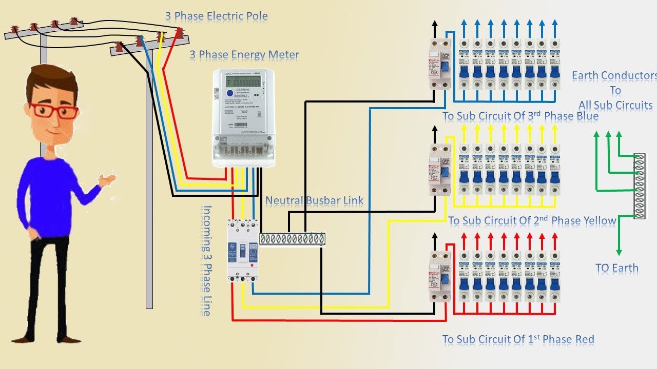
3 Phase Line Wiring Installation Single Phase Line In House | House

How 3 Phase Motor Control Circuit Works

How to Wire 120V & 208V Main Panel? 3-Φ Load Center Wiring

Circuit Analysis of 3 Phase System - Balanced Condition - Circuit Globe

Why Three-phase Voltage is 440 Volts? - Electrical Basics